Power Cycling Test Stations for Power Semiconductors
Thermomechanical lifetime qualification of your power modules
Overview
Our power cycling test stations verify the thermomechanical lifetime of power semiconductor modules — automated, over weeks and months, without user intervention. The system monitors each device individually, detects degradation early and documents the entire test history seamlessly.
What is tested
A load current heats the chip, switching off lets it cool down. These temperature cycles create mechanical stress at the material interfaces inside the module — particularly at bond wires, solder layers and the chip metallization. The test provokes exactly the failure mechanisms that also occur in real operation, only accelerated.
Two test modes cover different weak points:
- Short cycles (PCsec): Second-long heating pulses primarily stress bond wires and chip surface
- Long cycles (PCmin): Minute-long heating tests deeper solder layers and package attachment
Built for continuous operation
Over decades, Schuster Elektronik has built power cycling test stations for customers in module development, quality assurance and production support — across Europe, North America and Asia. Our systems typically run 24/7 over several weeks — PLC-controlled, with automatic limit monitoring and remote access via network. When anomalies occur, the operator is notified by email without anyone needing to be present at the equipment.
Our systems at a glance
- Load currents from 10 A to 2000 A
- Up to 36 test stations per system in independent strings
- Automatic Zth comparison via VCE(T) method
- Suitable for IGBT, MOSFET, SiC-MOSFET, diodes and thyristors
- Network interface for remote monitoring and data export
- Designed for AQG 324 (PCsec and PCmin)
Our Power Cycling Test Stations
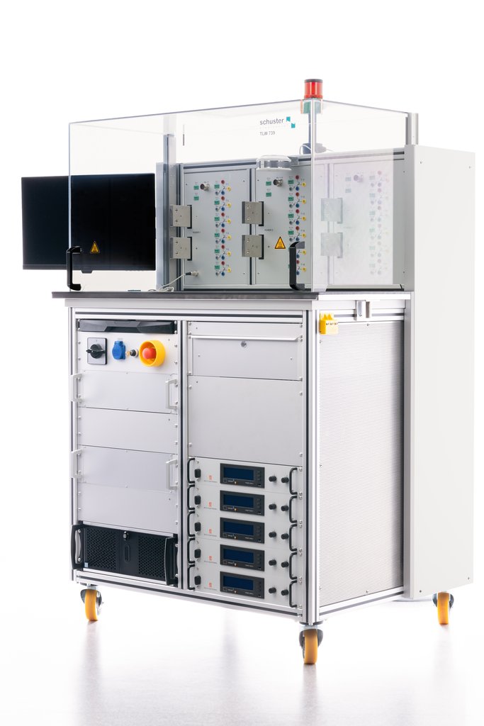
TLW 739
TEST SYSTEM FOR STABILITY OF SEMICONDUCTOR MODULES UNDER LOAD CHANGE

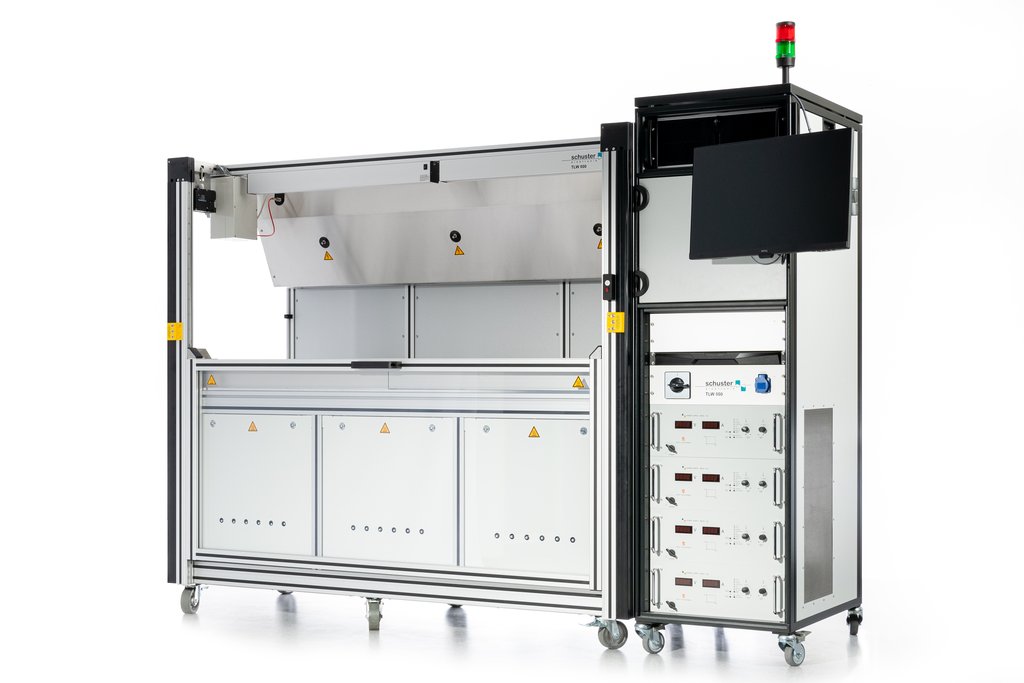
TLW 763
LOAD CYCLE TESTER FOR POWER SEMICONDUCTORS
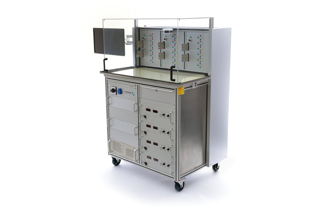
TLW 800
TEST SYSTEM FOR STABILITY OF SEMICONDUCTOR MODULES UNDER LOAD CHANGE
TLW 813
LOAD CYCLE TESTER FOR POWER SEMICONDUCTORS
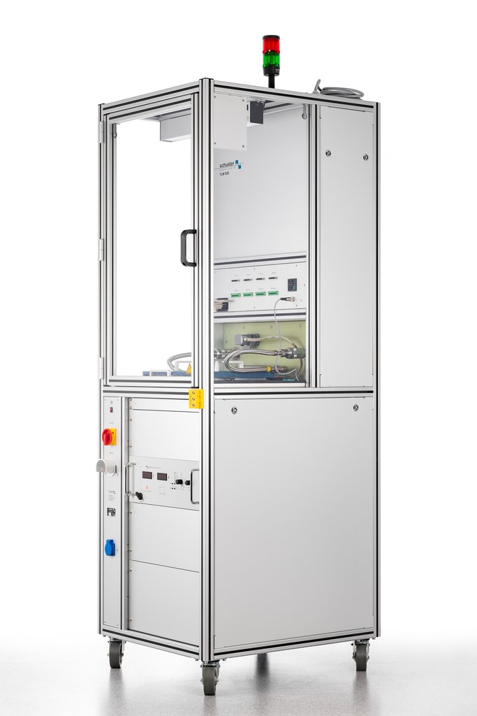
TLW 820
LOAD CYCLE TESTER FOR POWER SEMICONDUCTORS
Frequently Asked Questions
01 What exactly happens during a power cycling test and which failure mechanisms are provoked?
During active power cycling, the device under test (DUT) is periodically heated by its own forward current and cooled during the off-phase by a cooling system. The resulting cyclic temperature swings (ΔTj) create thermomechanical stresses at interfaces between materials with different thermal expansion coefficients. Typical failure mechanisms are:
- Bond Wire Lift-off: Different thermal expansion of aluminum bond wire and chip surface creates shear stress leading to bond detachment. Manifests as increase in forward voltage VCE(sat).
- Chip Metallization Degradation: Recrystallization and crack formation in aluminum metallization on the chip, accelerated by high temperature swings.
- Solder Fatigue: Crack propagation in solder joints between chip and DCB substrate (die attach) and between substrate and baseplate. Manifests as increase in thermal resistance Rth(j-c).
02 What distinguishes PCsec from PCmin per AQG 324 and when is each mode used?
The ECPE guideline AQG 324 defines two different power cycling modes that target different failure mechanisms:
- PCsec (ton < 5 s): Short heating pulses create steep temperature gradients that primarily stress chip-near connections -- bond wires, chip metallization and the upper solder layer (die attach). This mode simulates applications with fast load changes like motor inverters.
- PCmin (ton > 15 s to minutes): Longer heating times allow heat to penetrate deep into the assembly structure. Thermal stress extends to substrate, baseplate solder and package attachment. This mode is relevant for applications with slower load cycles.
The end-of-life criteria per AQG 324: +5% increase in VCE(sat) or +20% increase in Rth compared to initial value.
03 How is junction temperature measured in a power cycling test?
The standard method is the VCE(T) method (also TSEP method -- Temperature Sensitive Electrical Parameter). The semiconductor itself serves as temperature sensor:
- Calibration curve: Before testing, the temperature-dependent forward voltage VCE is recorded at a defined measurement current (typically 1-500 mA) for various temperatures.
- Measurement during test: After each load cycle, the load current is switched off and a small measurement current is applied. The measured forward voltage is converted to virtual junction temperature Tvj via the calibration curve.
- Zth determination: From the cooling curve Tvj(t), the transient thermal impedance Zth(t) can be calculated -- a sensitive indicator for incipient solder layer degradation before the steady-state Rth changes measurably.
For SiC MOSFETs, the calibration curve behaves differently depending on gate bias conditions (VGS = 0 V vs. VGS = -10 V) and may shift with aging.
04 What special requirements do SiC and GaN modules place on power cycling tests?
Wide-bandgap semiconductors differ from conventional Si-IGBTs in several aspects:
- Higher operating temperatures: SiC modules can be qualified at junction temperatures up to 200°C and above. The test system must reliably measure and control these temperatures.
- Different assembly technologies: Modern SiC modules often use sintered chip attachments (silver sinter instead of solder) and copper bond wire instead of aluminum. These connection technologies have different fatigue characteristics and require adapted test parameters.
- Smaller chip areas: At equal current carrying capability, SiC chips are significantly smaller than Si-IGBTs, leading to higher local heat flux densities.
- Calibration curve stability: For SiC MOSFETs, the VCE(T) calibration curve may shift due to gate oxide aging (threshold voltage drift), affecting temperature measurement.
05 What measurement infrastructure do Schuster Elektronik power cycling test stations offer?
Our systems provide complete measurement infrastructure for standards-compliant power cycling tests:
- Load current generation: 10 A to 2000 A, configurable to module requirements
- Measurement current source: up to 5000 mA for the VCE(T) method, including automatic calibration curve determination
- Test stations: up to 36 measurement points in 3 independent strings (TLW 800), up to 20 test stations in one string (TLW 820)
- Temperature measurement: Type K thermocouples at each test station plus string temperatures
- Cooling: Individually controllable water cooling circuits per string with PT100 sensors
- Optional: Recording of cooling curves and transient Zth measurement
- Data management: PLC-controlled continuous operation with automatic recording, email notification on test interruptions, network interface for remote access
- Safety: Protective hood with safety interlock, automatic limit monitoring
Inquiry about Power cycling test station
Interested in products or updates in the field of Power cycling test station? Contact us — we're happy to advise you.